DIY audio amplifiers offer audio enthusiasts and hobbyists a rewarding and engaging experience. Building an amplifier not only allows you to customize the sound to your liking but also provides a deeper understanding of the components and principles behind amplification.
This article is a comprehensive guide for beginners, outlining the basic concepts, performance requirements, design principles, module unit details, component selection, assembly techniques, testing procedures, and considerations for creating your audio amplifier.
Whether you’re a music lover, a repair person, or an audiophile looking to delve deeper into audio amplifiers, this article will provide the basic knowledge and skills necessary to build a successful DIY audio amplifier project.
The Basics of Audio Amplification
What is an audio amplifier?
Before we dive into the details of building your audio amplifier, let’s quickly review the basics.
An audio amplifier is a device that increases the strength or amplitude of an audio signal. It takes a low-power audio signal, such as one from an MP3 or cell phone, and boosts it to a level that can drive speakers. This amplified signal allows you to enjoy your favorite music at a higher volume without distortion or loss of quality.
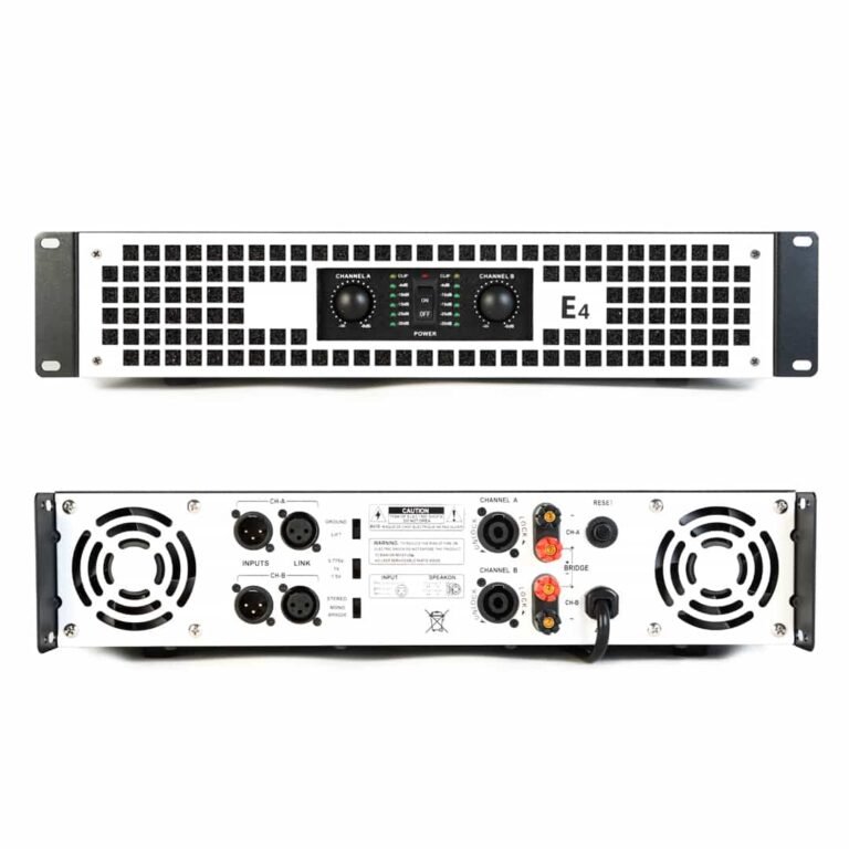
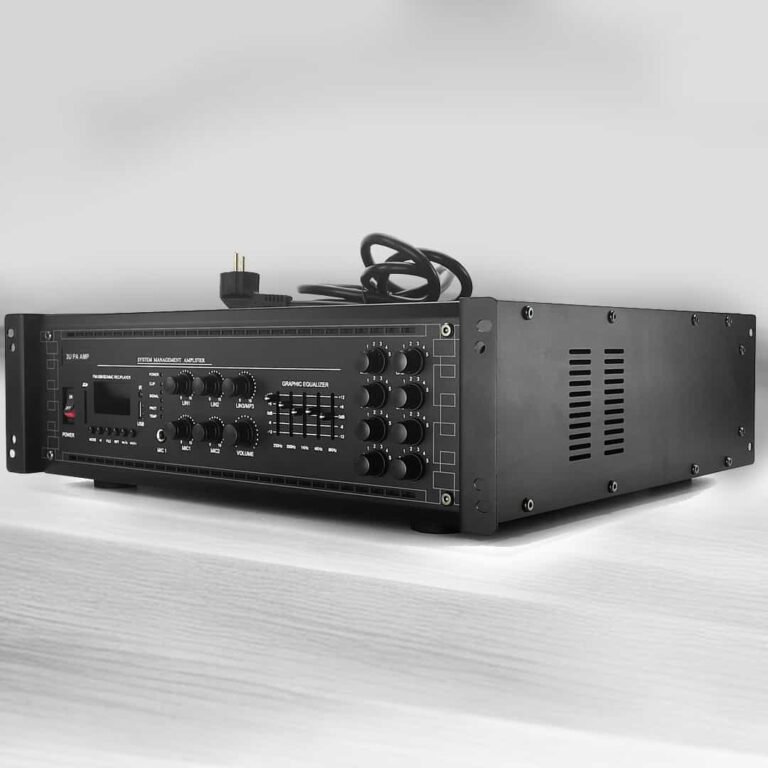
Typically, audio amplifiers include stage amplifiers, public address amplifiers, and home stereo amplifiers.
Performance Requirement
Design and assemble an audio amplification circuit to amplify the music signal output by the MP3 player. It also has an equalization circuit that can adjust the high and low frequencies of the sound source signal. In addition, an electronic switch needs to be designed to choose between two audio sources.
The basic performance indicators are required to be:
Minimum output power: 5W;
Output impedance: RL=8 Ω;
Input impedance:>600 Ω;
1. The power amplifier has two MP3 output input connectors;
It needs to have two audio inputs. The MP3 output music signal is a small analog signal with an amplitude of about 5mv~10mv.
2. It is capable of using electronic switches for audio source selection and can be indicated by light-emitting diodes
When there are two music signal inputs, the electronic switch can select between the two music signals and indicate the selected audio source using a light-emitting diode.
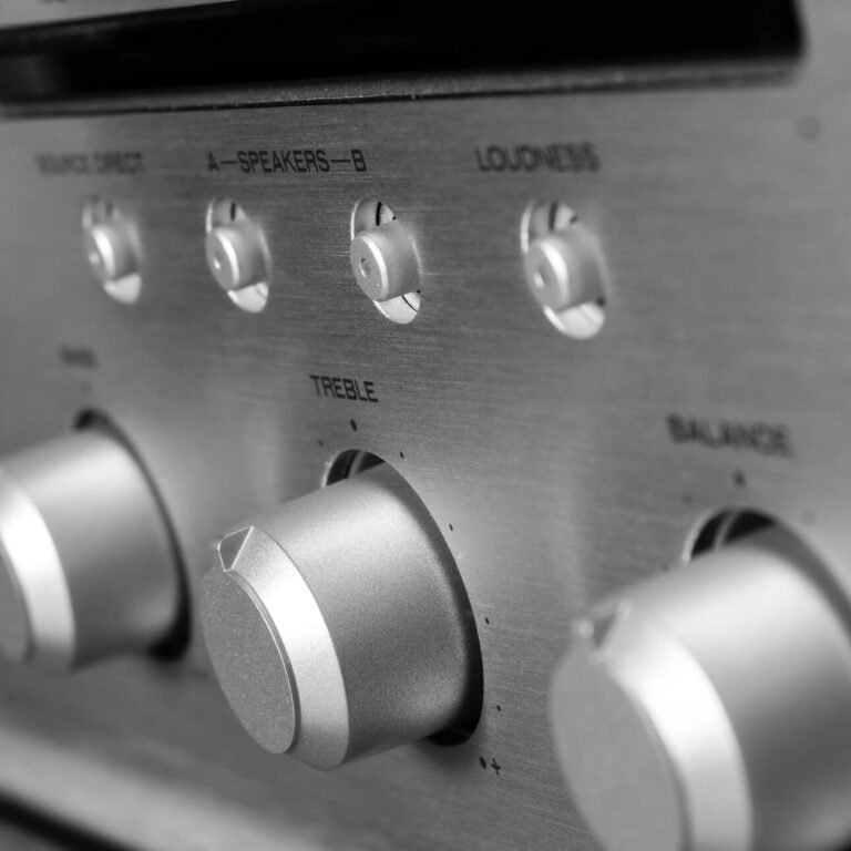
3. The audio amplifier is equipped with volume control and power amplification functions
In the design of the circuit to get the output signal volume control, and to realize the amplification of the signal, in the input of the speaker to design the power amplification device.
4. The main technical specifications are as follows:
- Rated output power: 2x5W (THD ≤ 0.5%)
- Load impedance: 8Ω
- Input impedance: >600Ω
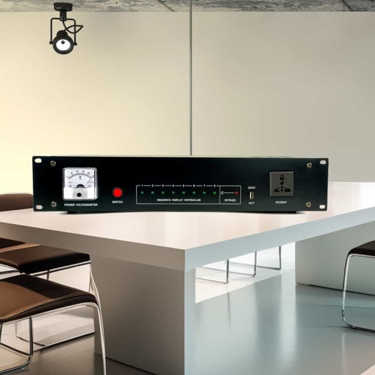
5. Power supply: 220V/50HZ AC power supply;
6. According to the above technical requirements to design the circuit, drawing circuit diagrams, the designed circuit with Multisim or OrCAD/PspiceAD9.2 simulation, with universal board welding components, production circuits, complete debugging, testing.
7. Design equalization circuits (tone circuits)
8. With level indication function
Design Principles
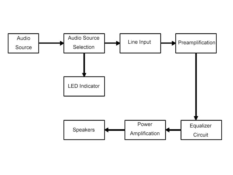
The audio signal from MP3 is selected by the selection circuit composed of analog switch CD4066BD and sent to the preamplifier for voltage amplification, and the diode display circuit composed of a T-trigger displays the selected audio source.
Next, the audio source is equalized by the RC4558 equalization circuit for high and low-frequency equalization, and then by the TDA2822 power amplifier for power amplification to make the speaker work.
The design has a sound source selection, amplification, and other functions, the principle block diagram is shown below:
Module Unit Details
Audio Source Selection Circuit
Circuit structure and working principle
In professional power amplifiers, there are usually multiple inputs for external audio sources. Typically, there are mechanical, relay, and electronic ways to select one of these sources.
The mechanical type selects a sound source by turning the selection switch. It is a simple circuit, and sound channel isolation is good, but the quality of the selector switch is more demanding. Because frequent toggle selector switch makes it easy to make the switch aging, thus affecting the performance of the whole machine.
The relay type replaces the mechanical selector switch with a relay and corresponding driving circuit. It is good for sound channel isolation, but the assembly is more complex, in addition, there is a certain electromagnetic interference, so it is rarely used.
The electronic type is an analog electronic switch using electronic circuits to select the audio source. Electronic selection circuit design is flexible, easy to assemble, and more widely used. The disadvantage of this design is that the channel isolation is slightly lower, but in general sufficient to meet the requirements. This audio amplifier uses the electronic type for the audio source selection circuit. Below is the circuit simulation.
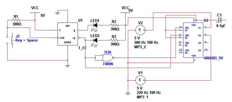
Audio source selection circuit simulation diagram
Pre-Amplifier Circuit
Circuit structure and working principle
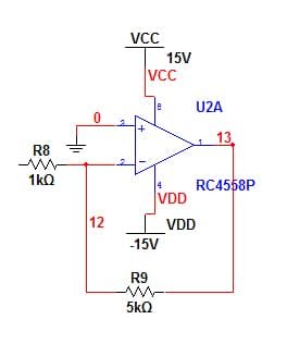
The preamplifier is a linear amplification of the source signal to meet the input signal amplitude requirements of the subsequent amplifier stage. The preamplifier is composed of an operational amplifier or separate components, this design selection of integrated operational amplifier RC4558 constitutes a pre-amplifier.
Voltage gain: Au=- R5/R6=5
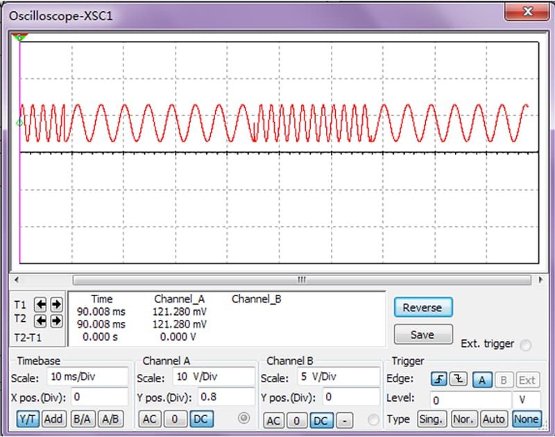
Preamplifier Circuit Simulation Waveforms
Equalization Circuit
Circuit structure and working principle
The function of the equalization circuit is to adjust the frequency response of the output signal of the audio amplifier according to certain rules according to the need, to achieve the purpose of compensating the acoustic characteristics and beautifying the timbre. It can enhance and attenuate several frequency band points in the audio range respectively. The ideal frequency characteristic control curve for a certain frequency band point is shown below, and the dotted line is the actual frequency characteristic control curve.
f0 = 1kHz
Midrange frequency (also called center frequency), midrange gain Au = 0dB;
fl1
Bass turning frequency, generally a few tens of Hertz;
fL2 = 10fL1
Midrange turning frequency;
fH1
Mid-tone turning frequency;
fH2 = 10fH1
Treble turning frequency, typically a few tens of kilohertz.
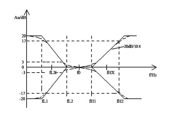
Ideal frequency characteristic control curve at a certain band point
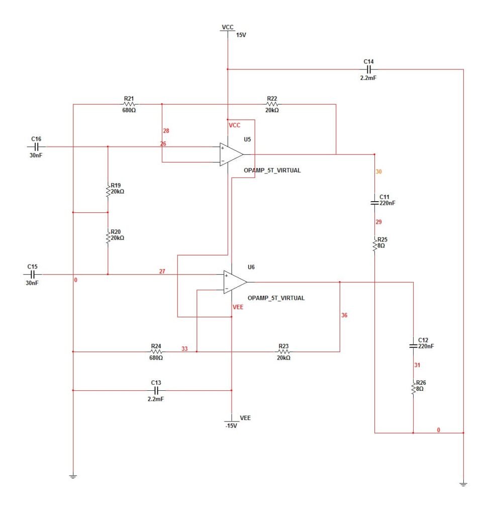
An equalization circuit serves to perform tone control, usually by boosting or attenuating the gain of certain frequency points in the high or low frequencies of an amplifier while keeping the midrange frequencies unchanged. It is often composed of low-pass, high-pass, and band-pass filters. The figure below shows an equalization circuit with treble and bass adjustments consisting of an op-amp RC4558 that boosts or attenuates high and low frequencies.
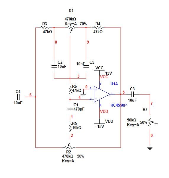
Equalization Circuit Composed of Op-amp RC4558
RP3 is the bass adjustment potentiometer, turn counterclockwise to the end, and the low-frequency boost is maximum;
RP5 is the treble adjustment potentiometer, turn counterclockwise to the end, and the high-frequency boost is maximum;
RP4 is the volume adjustment potentiometer.
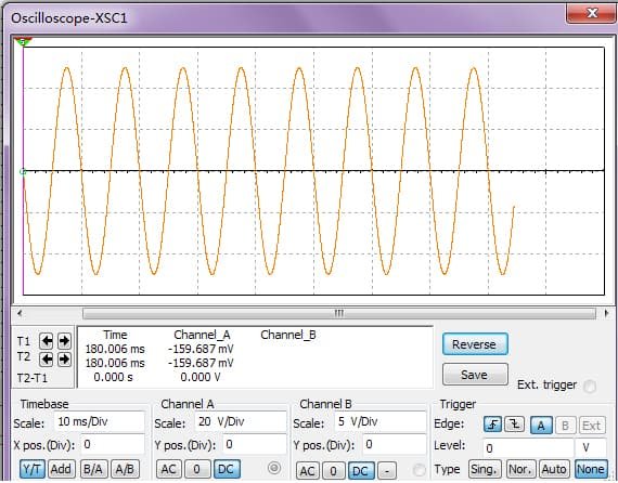
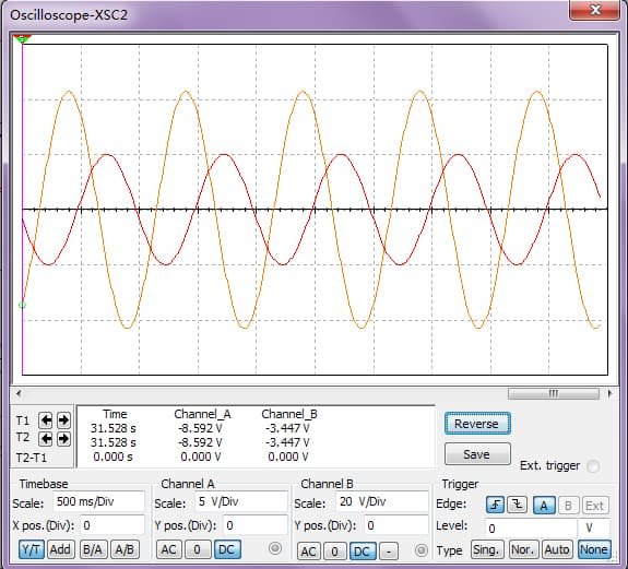
Equalizer Simulation Waveforms
Power Amplifier Circuit
Circuit structure and working principle
The role of the power amplifier stage is to power amplify the signal from the equalization, this design uses an integrated power amplifier TDA1521. TDA1521 is a dual-channel amplifier produced by Philips. It can work with a single power supply, and can also work with a dual power supply, in ± 16V power supply can be obtained 2x12W power. It is internally set up with overheating protection and a squelch circuit, turned on or off instantly with a squelch function, and can be turned on or off instantly to inhibit unwanted inputs to protect the amplifier and speakers. The integrated power amplifier circuit has excellent performance and simple peripheral circuitry and is widely used in the audio signal amplifier circuit of large-screen televisions, as well as other audio equipment.
power amplifier circuit
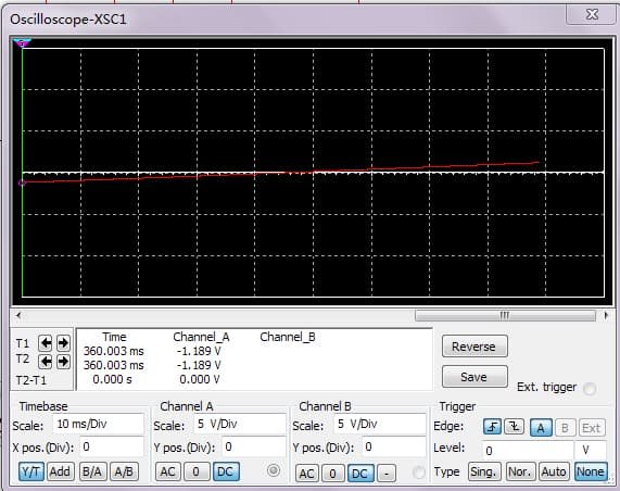
Power amplifier circuit waveform simulation
Channel A is the output signal and channel B is the input signal, from the waveform it can be seen that the input signal is amplified by the whole circuit.
Component Selection and Parameters
As the required output power of 2 × 5W 2 channel power amplifier, the power amplifier can be selected TDA1521, operational amplifier can be selected general-purpose dual operational amplifier RC4558.
Electrolytic capacitors use aluminum electrolytic capacitors, and withstand voltage is selected 25V.
Film capacitors are selected polyester film capacitors, that withstand voltage selection 50V or 63V.
Resistors R13 and R14 selected RJ series 10Ω/1W resistors, other resistors are selected RT14 series 1/4W, 10% precision carbon film resistors. The other resistors are RT14 series 1/4W, 10% precision carbon film resistors. 1/4W metal film resistors are also available.
Potentiometers RP3 and RP5 are carbon film potentiometers.
The RP4 uses coaxial potentiometers to control the volume of the left and right channels simultaneously.
System gain (dB) should be the sum of the unit circuit gain (dB).TDA1521Z in the rated output, if RL = 8Ω, ± VCC = ± 16V, then the maximum undistorted output voltage is Uom = 10V.
The system voltage gain is 66dB.
By the above selection of component parameters, the gain of the equalization circuit has been designed for 0dB. Power amplifier TDA1521 within the 30dB gain, the gain of the preamplifier can be selected as 20dB, which can determine the value of the resistor in the preamplifier. In this design of the audio amplifier, the preamplifier gain is selected as about 5dB, that is, R4 = R6 = 10K, R5 = R7 = 47K.
Installation and Commissioning of Circuits
The audio power amplifier is a small circuit system, before the installation of the various levels of reasonable layout, generally by the circuit of the order of the layout of the first level, the amplifier stage should be far away from the input stage, each level of the ground as far as possible to be connected, connecting the wires as short as possible. Otherwise, it is easy to appear self-excitation.
The quality of the components should be checked and tested before installation, and special attention should be paid to the amplifier block to add heat sinks and thermally conductive silicone grease. In addition, the pins and polarity of major components such as operational amplifiers and electrolytic capacitors should not be connected incorrectly. Starting from the input stage in turn to the backstage installation, but also from the amplifier stage can be installed step by step forward. To install a module, you need to debug it properly. After installing two modules, it needs to cascade debugging until the entire machine is installed and debugged.
Circuit Debugging
After the installation of the circuit is completed, a detailed inspection of the circuit should be carried out to confirm that the installation is correct before power can be applied. After powering on, check the circuit for obvious abnormalities. If there is any abnormal phenomenon, it indicates a malfunction and should be eliminated. If there are no abnormal phenomena, debugging can start. When debugging, first perform hierarchical debugging, and then cascade debugging. Hierarchical debugging is divided into static debugging and dynamic debugging.
Static debugging
Short-circuit the signal input to ground, and measure the DC voltage of the key points at all levels of the circuit to see if it is normal. For example, when the op-amp is symmetrically supplied to the positive and negative power supplies, the DC level at the output point should be 0 V. If it is not 0 V, there is a fault in the circuit, so check whether the circuit has a self-excitation phenomenon and eliminate it.
Dynamic debugging
Connect input signals (usually sine wave signals of certain amplitude and frequency) to the input terminals of each circuit segment, observe the waveform at key points whether is normal, and if there are faults, check and promptly eliminate them.
Cascade commissioning
After dynamic debugging is completed, each segment can be connected for cascade debugging. After confirming that there is no abnormality in the circuit, input a 5-10mV sinusoidal signal at the input to check whether the circuit of each segment is normal. If it is not normal, start from the previous section, step-by-step backward check, and troubleshooting. Then adjust each potentiometer to check for control and correct control.
System Performance Testing
Rated Power
The maximum power at which an audio amplifier’s output distortion is less than a certain value (e.g., THD <5%) is called the rated power. The formula is P=U^2/R
In this formula, R is the rated load impedance; U (RMS) is the maximum undistorted voltage across R.
To measure P, connect a rated load resistor R to the output of the power amplifier (instead of a loudspeaker), and gradually increase the input voltage until the waveform of U is just free of clipping distortion (or THD <5%). At this time the corresponding output voltage is the maximum output voltage. From the above formula, you can calculate the rated power P. Please note the maximum output voltage should be reduced quickly after testing, otherwise, the power amplifier will be damaged due to the measurement time being too long.
Frequency Response
The bass frequency fL and treble frequency fH corresponding to a 3dB decrease in the voltage gain of the amplifier relative to the voltage gain of the midrange tone fo (1kHz) is called the frequency response of the amplifier.
Firstly, adjust the volume control potentiometer so that the output voltage is approximately 50% of the maximum output voltage.
Then measure the voltage gain Auo about 0dB at 1kHz, and then measure the low-frequency characteristics and high-frequency characteristics.
Measure the low-frequency characteristics: Place the slide arm of RP1 at the leftmost end and RP2 at the center position, change the frequency from 20Hz to 1kHz, and note down the corresponding voltage gain (low-frequency boost). Then place the slide arm of RP1 at the rightmost end, the frequency changes from 20Hz to 1kHz, and note down the corresponding voltage gain (low-frequency attenuation).
Similarly, to measure the high-frequency characteristics, the slide arm of RP2 is placed at the leftmost and rightmost ends, RP1 is placed in the middle position, and the frequency is changed from 1kHz to 20kHz, which corresponds to the high-frequency boost and high-frequency attenuation, respectively, and the corresponding voltage gain is noted down.
Finally, the tone controller characteristic curve is plotted and the voltage gains corresponding to the frequencies fL1, fL2, fo (1kHz), fH1, and fH2 are labeled.
Input Impedance
The impedance from the input of an audio amplifier is called the input impedance Ri, and Ri is measured in the same way as the input impedance of an amplifier.
Noise voltage
When the input of the audio amplifier is zero, the voltage on the output load RL is called the noise voltage Un. The measurement method is to short-circuit the input terminal to ground, set the volume potentiometer to its maximum value, observe the voltage waveform of the output load RL with an oscilloscope, and measure its RMS value with an AC voltmeter.
Overall Efficiency
η= Po/Pcx100%
In this formula, Po is the rated power output; Pc is the power consumption of the power supply when outputting the rated power;
Safety Precautions for DIY Amplifier Projects
Understanding Electrical Safety Measures
When working on your DIY amplifier, make sure to prioritize safety. Always disconnect the power supply before making any modifications or measurements. Avoid working with high voltages unless you have the necessary knowledge and experience.
Proper Handling and Disposal of Electronic Components
When it comes to handling electronic components, a gentle touch goes a long way. Avoid static electricity by using an antistatic wrist strap or mat. Take care not to excessively bend or strain delicate components. When it’s time to retire components, consider recycling them properly to protect the environment.
Protecting Yourself from High Voltage and Current Risks
Always double-check that your amplifier is properly grounded and that safety measures, such as fuses, are in place. Never play with electricity if you’re unsure about what you’re doing. Stay safe and enjoy your DIY journey.
DIY Audio Amplifier Summary and Next Poject
You now have the basic knowledge and skills to start your DIY audio amplifier. With the detailed explanation of the steps above, you are ready to create a small amplifier with basic functionality. Remember to always prioritize safety and follow proper operating procedures when building electronics. As you continue to explore and experiment, you can further improve the performance of your amplifier and explore new customization options.
For more in-depth exploration and how-to videos, please contact us via email:info@vipsounds.com